Concepts and terminology
Before starting to use Piping Isometrics & Spools, make sure you are familiar with the following concepts and terminology.
Isometric drawing terminology
Attributes
Attributes store information about objects. For example, a component model can have attributes like "Component type" and "Manufacturer". Attributes are not object type specific: same attribute can be assigned to several object types. Therefore, you can manage attributes in two ways: via the object types they are assigned to, or directly in Manage COS.
Tags
Tags are attributes of parts and points. They usually come from Plant Modeller and describe some properties of parts and points, such as valve position or welding of a joint.
Labels
A label is a 2D symbol or text that is placed on the drawing sheet and linked to a piping object. The purpose of a label is to visualize a piece of information about the piping object. The information that is shown in the label can be data extracted from the database, like the nominal size of the pipe, or it can be visual, like a flow arrow on a pipe run.
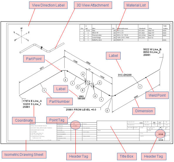
The picture below shows different kinds of annotations on a drawing sheet.
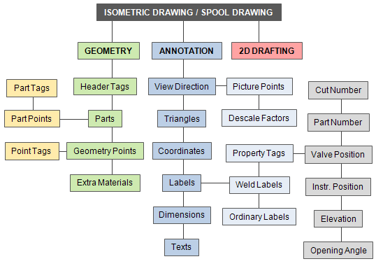
Data structure in Piping Isometrics & Spools
To be able to run Piping Isometrics & Spools, you should have a properly configured the CADMATIC project that contains your user workspace. In the workspace, you have one design area for Piping Isometrics & Spools. The design area represents the data set used by a single Piping Isometrics & Spools session. Next, we describe how the data set is organized.
Level 1: Isometric & spool drawing
-
An isometric drawing collects a number of (usually connected) piping components and the associated information that are to be annotated in Piping Isometrics & Spools as a single unit.
-
Spools function as a grouping mechanism within an isometric but behave like an isometric drawing.
Level 2: Geometry, annotation and 2D drafting
-
Geometry stores information about parts, attributes (tags) assigned to the whole geometry or to a specific part, and the location and the linking of the parts. It represents the physical model that is the subject of the drawing.
-
Annotation objects create the visual parts of isometrics and spool drawings.
-
2D drafting objects can be inserted into the drawing area of the isometric sheet. This is useful, for example, when one needs to draw a particular detail on the sheet.
Pipe geometry concepts
The geometrical model of a pipe consists of a set of piping objects that can be, for example, straight pipes, elbows, flanges, and valves that are joined together. The geometry can include all the components of the whole pipeline, or the pipeline can be divided into several separate geometries. Each geometry represents one isometric drawing.
![]()
A piping object represents its real-world counterpart with the following attributes:
-
Symbol (defined in the Piping Isometrics & Spools symbol map)
-
Geometry type, which defines the points to which other objects can be connected
-
Geometric location
-
Orientation
-
Other parameters defined in Dimension Tables
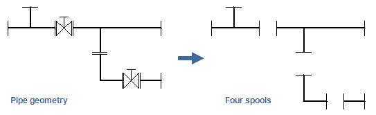
The pipe geometry can be divided into spools. A spool is a group of connected objects that are prefabricated as a unit and installed in the target environment as one piece. If the pipe geometry takes too much space in isometric drawings, the geometry can be divided into smaller pieces for visual purposes (= splitting).
The picture below illustrates how piping components can appear in drawings.
Plant Modeller can generate pipe geometries for the Piping Isometrics & Spools application, as described in Piping Isometrics.
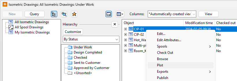
Plotting and exporting
You can plot or export drawings that are checked out to you. Exporting uses a predefined format, scale, and output directory. Plotting prompts for the plotter, if there is no preselected printer for the sheet.
You can preselect a printer and plot settings for every sheet individually. These selections are user-specific (design area specific) settings. Use Settings > Printer Preselection for Sheet to modify the settings for the drawing sheet.
